Jeep
Note
This is NOT A FULL LIST of features available for modification, rather a colletion of more complex, vehicle-specific settings. For a complete list of features go to the JScan app and use demo mode connection.
Wrangler JK (2007-2018)
Installing LED Fog Lights
JScan can’t help much here, but please see this great guide on installing LED fog lights in your JK.
Sway Bar removal
Note
DO NOT access the Sway Bar module to disable it. That’s not how it works.
Go to Adaptation section
- Use the search and find:
ASBS Sway Bar On/Off
Disable it
Turn the ignition off, restart the vehicle.
In case there are still errors, run Advanced Scan and clear them.
TPMS
Follow the generic TPMS instructions.
US -> EU Light conversion
If you imported a JK from the USA, you will need to adapt (among other things) the rear lights. In American version the stop light is also the turn signal. In Europe, these need to be separated.
Connect to your vehicle
Open Adaptation
Open “Lights conversion US<->EURO & LED”
Set “Rear Lighting Combined On/Off” to disabled
Now your side lamps will work as indicators only, and you need to route a wire from the third (central) stop light to each of the rear lamps to power the European stop lights as well.
Enable Front Fog Lights with High Beam
This procedure allows the front fog lights to remain ON when high beam headlights are activated in Jeep Wrangler JK vehicles.
From factory configuration, fog lights automatically turn OFF when high beams are enabled. Using JScan, this behavior can be modified through the Front Control module (TIPM).
Procedure
Turn ignition to RUN (engine OFF).
Connect JScan to the vehicle.
Open the Front Control (TIPM) module.
Navigate to Configuration.
Search for the setting related to fog light behavior with high beams (e.g. Fog Lights Drop Out With High Beam or similar wording).
Change the setting to Disabled (or equivalent option allowing fog lights to stay ON).
Confirm and write the configuration to the vehicle.
After Completion
Turn ignition OFF.
Wait at least 30 seconds.
Turn ignition back to RUN.
Verify that fog lights remain ON when high beams are activated.
Clear any stored Diagnostic Trouble Codes (DTCs) if necessary.
Important Notes
This modification changes factory lighting behavior.
Ensure compliance with local road regulations before enabling this feature.
Some regional configurations may use slightly different naming for the setting.
Transmission gear ratio
Change this only if you physically changed the gears. Make sure you know the actual ratio (don’t trust the labels on boxes).
Connect to your vehicle
Open Adaptation
Open “Tire & Axle Settings”
Change T-Case High and/or T-Case Low Ratio
Execute Initialize EGS
Note
For WA580 - NAG1 automatic transmission only. This step is not required in JK 3.8 with an older transmission (it doesn’t have the EGS).
Turn off the vehicle
Close & lock the door and leave the vehicle for a 15 min break
Go for a test drive
Note
If there are errors mentioning “incorrect gear ratio” see Troubleshooting
Jeep Wrangler JK Automatic transmissions
Below you will find tech tips and procedures dedicated for each gearbox. There were 3 automatic gearboxes in JK 42RLE (4 speed), 545RFE (5 speed), WA580/NAG1 (5 speed)
JK 2.8 CRD 2007 - 2010 - 545RFE
JK 2.8 CRD 2010 - 2018 - WA580/NAG1
JK 3.8 Petrol - 2007-2011 - 42RLE
JK 3.6 Petrol - 2011 - 2018 - WA580/NAG1
545RFE
The 545RFE transmission has its own transmission control unit Procedures:
“Quick Learn” - Quick Learn should only be used when a transmission has been replaced or overhauled, or when the Transmission Control Module has been replaced or flashed.
“Clear VLP Counters” - Shift Counters
“Clear VLP Counters” - Tooth Counters
42RLE
The 42RLE gearbox has a gearbox controller connected to the engine control unit (all in one module) Procedures:
“Quick Learn” - Quick Learn should only be used when a transmission has been replaced or overhauled, or when the Transmission Control Module has been replaced or flashed.
“Clear VLP Counters” - Shift Counters
“Clear VLP Counters” - Tooth Counters
WA580/NAG1
The WA580 gearbox has its own gearbox control unit (it is roughly to the right of the driver’s feet) Procedures:
Initialize EGS - This procedure will transfer data in to transmission module, it is required when you update Axle Ratio and recommend with significant Tire Size update (if you experience poor shifting).
TCM Reset Learned Adaptives - This procedure This program allows the electronic transmission system to re-calibrate itself.
TCM Store Learned Adaptives - This procedure This program allows the electronic transmission system to save current calibrations.
See NAG1 How-To for details.
Setting the Steering Angle
There is no such thing as an software initialization procedure for the steering angle sensor. If the wheels are straight and the steering column is assembled right, it will read 0.
General hints on handling steering angle issues:
Connect > go to modules > ABS > Live Data > (…) > search for steering angle > select > OK > PLAY
If your wheels are straight it should show 0
If it shows 180, the steering column part is upside down
If it is OK - start the engine, make a full turn left, full turn right. Switch back the key to RUN (engine off) > Run Advanced Scan, see if you have any further errors.
If the steering angle is off by a different number than ~180 you’ll have to inspect the steering system.
ABS Pump Bleed
It’s PUMP bleed, not a full brake sytem bleed. It’s to be done after a regular brake bleed.
Note
Yes, it does bleed only one side. By design.
Changing the radiator fan trigger temperature
This is not a setting that can be configured with JScan. There are other tools, which modify the engine controller software / do tuning, that can do it, but this is beyond the scope of JScan app.
Axle Ratio change
Changing the axle ratio works in a similar way on the vehicles that support it. What is important though are the steps AFTER making the changes.
Attention
Make sure your engine is NOT RUNNING
Connect to your vehicle
Wait for the VIN to be discovered
Open Adaptation
Open Tire & Axle settings.
Open Axle Ratio
Read the help (?) if present
Choose a value from the drop-down list.
Note
If you pick a value that doesn’t match the actual physical gears, you will be getting all sorts of gear ratio errors once you start driving.
Tap Go
Once done, follow the steps indicated in the help section. For example, on the JK Wrangler (automatic transmission) this means:
Do not drive yet
Run the Initialize EGS adaptation
Follow the instructions on screen
When procedure is completed turn ignition to off. Leave the car, close & lock the door. Take a 5 min break.
After 5 min, start the car and do a test drive and check if all is fine. If you have any problems, check troubleshooting section.
Notes:
If you’ve installed Dana 60 axles on a model equiped with Dana 30 or 44 model, you will need to consider the difference in ABS tone ring tooth count (60 vs 52).
There are two ways of handling this:
Easier:
You can set the axle ratio & tire size to a value multiplied by 0.86666~ (60/52) to cheat the system. For Example:
Gear Ratio Calculations:
5.38 x 0.8666666666666667 = 4.66 5.13 x 0.8666666666666667 = 4.45 4.88 x 0.8666666666666667 = 4.23
Tire Size Calculations:
42 x 0.8666666666666667 = 36.40 40 x 0.8666666666666667 = 34.67 37 x 0.8666666666666667 = 32.07
More complex:
This method is not 100% confirmed, but theoretically is the proper way to address the tone ring tooth count difference.
After changing the axle ratio and initialising EGS:
Go to JScan settings > App & Adapter settings
Enable ‘Show advanced adaptations’
Restart the app
Connect to the vehicle
Go to Adaptation > Tire & Axle settings
You will see two new adaptations:
ABS Front Tone Wheel Teeth Count
ABS Rear Tone Wheel Teet Count
Set both of them to 60
Go to Adaptation > Vehicle Maintenance
Run ABS Initialization
If successful, turn the ignition to off, lock the door for 5 minutes. Take a break. After 5 minutes, go for a test drive.
Standalone 8HP Transmission Diagnostics (Wrangler JK Swap)
This guide explains how to connect JScan to a standalone ZF 8HP Transmission Control Module (TCM) installed as part of a transmission swap in a Jeep Wrangler JK.
Vehicles equipped with an aftermarket 8HP swap typically have two separate OBD-II diagnostic ports:
Factory OBD-II port - communicates with the original Wrangler modules (PCM, ABS, TIPM, etc.).
Transmission OBD-II port - communicates directly with the standalone Transmission Control Module (TCM).
To access transmission functions such as Shift Adaptation or Transmission Relearn, JScan must identify the transmission using the VIN stored in the TCM.
Configuration
Open App & Adapter Settings and configure the following options:
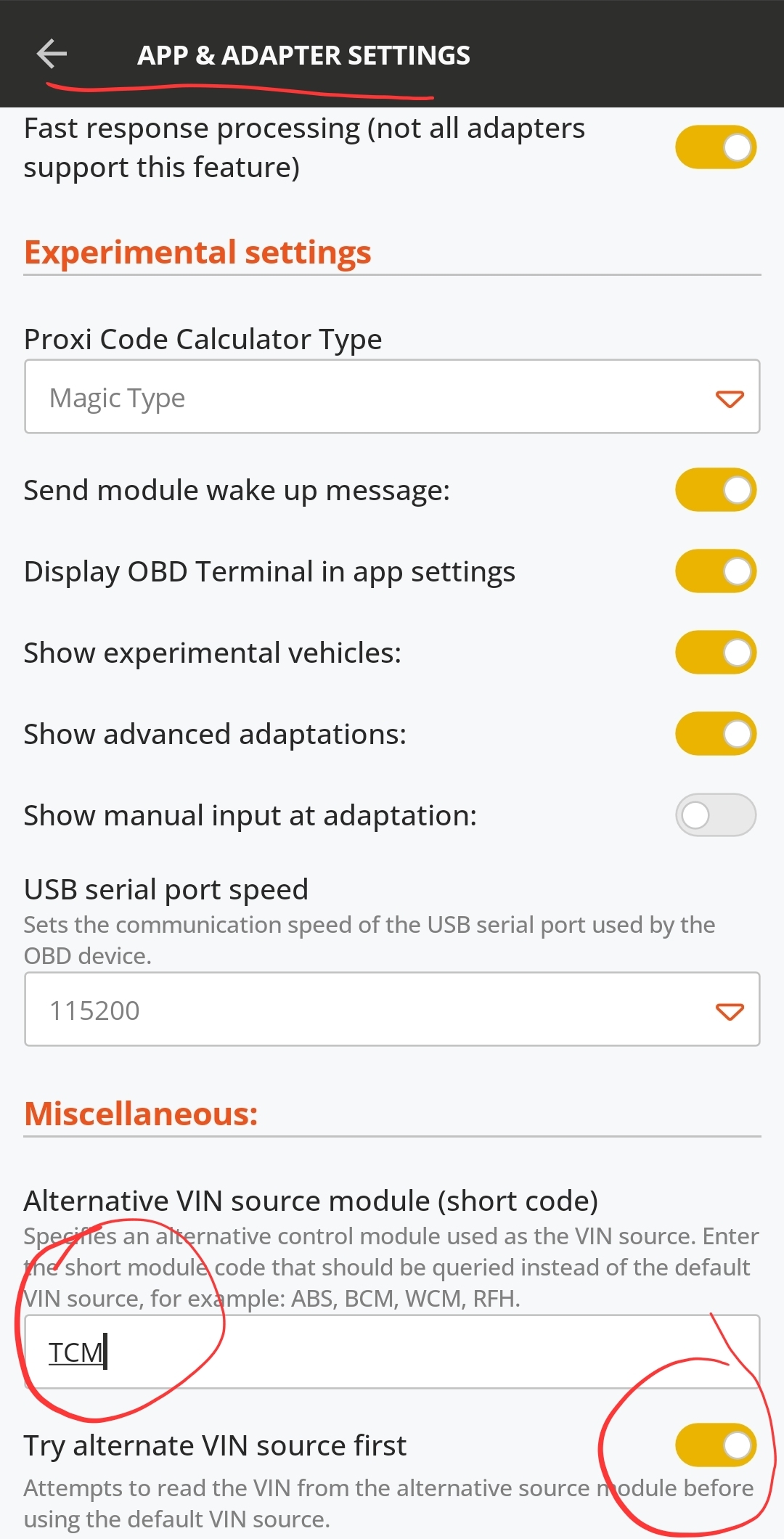
Configure the alternative VIN source to use the Transmission Control Module (TCM).
Set:
Alternative VIN source module (short code):
TCMEnable Try alternate VIN source first
These settings instruct JScan to read the VIN from the Transmission Control Module before querying the default vehicle modules.
Connecting to the Transmission
Connect the OBD adapter to the transmission OBD-II port.
Launch JScan.
At the vehicle selection screen, select the vehicle that matches the transmission donor, for example 2016 Dodge Challenger or 2016 Dodge Charger.
JScan will read the VIN from the TCM and establish communication with the transmission controller.
You can now perform transmission-specific diagnostics and service procedures, including:
Shift Adaptation
Relearn Procedures
Reading and clearing DTCs
Live Data
Adaptation Functions
Connecting to the Wrangler
To diagnose the Wrangler itself:
Connect the adapter to the factory OBD-II port.
Select Jeep Wrangler JK when starting JScan.
The application will communicate with the original Wrangler control modules using the factory VIN.
Note
The alternative VIN source configuration does not modify the vehicle. It only changes which control module JScan queries first when identifying the connected vehicle.
Summary
A Wrangler JK equipped with a standalone 8HP transmission swap uses two
independent diagnostic networks. By configuring the Alternative VIN Source
to TCM and enabling Try alternate VIN source first, JScan can
communicate directly with the transmission through the dedicated OBD-II port,
allowing full access to transmission diagnostics and adaptation procedures.
Wrangler JL (2018+)
Choosing the right adapter
Jeep JL (and JT) are quite advanced in terms of electronic systems installed in the vehicle. Some of these systems don’t operate on the standard CAN bus network, and to access them you will need either the Vlinker MS or vLinker MC+ OBD or Link MX+ adapter.
The affected modules are:
HVAC (Heat, Ventilation, Air Conditioning)
BSM (Blind Spot Module)
some other radio features
Bypassing the Security Gateway
Chrysler’s Secure Gateway Module came out in 2018. The SGW is a module whose function is simply to keep the communication networks secure. The SGW protects the vehicle networks from being exploited by creating a firewall between two portions of the network with the most vulnerability. This means, that to make any changes, you will need a SGW bypass - usually a cable. See our SGW Bypass page for details.
Jeep Wrangler JL/JT 2018+ Rear Lights Conversion US to EU
This procedure describes the general steps required to convert rear lamps on Jeep Wrangler JL/JT 2018+ from US specification to EU specification.
The conversion usually includes:
separating rear brake lights from rear turn signals,
enabling dedicated rear turn signal outputs in the BCM,
adding missing wires between the BCM and rear lamps,
installing EU specification rear lamps,
enabling rear fog lamp outputs,
replacing the light switch with an EU specification version when rear fog lamps are required.
Warning
This procedure requires physical wiring modifications. OBD JScan can only change the vehicle configuration. It cannot replace missing wires, connectors, lamps, or switches.
Warning
Always verify the wiring diagram for the exact vehicle year, body type, trim level, and lamp package before modifying the vehicle wiring. Incorrect wiring may damage the BCM or lighting components.
Required Parts
Depending on the vehicle equipment and the scope of conversion, the following parts may be required:
EU specification rear lamps,
additional wires from BCM to rear lamps,
BCM terminal pins,
KOSTAL 2.8 SLK terminals for rear turn signal outputs,
KOSTAL 1.2 MLK / SLK terminals for rear fog lamp outputs,
EU specification light switch with rear fog lamp function,
suitable OBD adapter supported by OBD JScan.
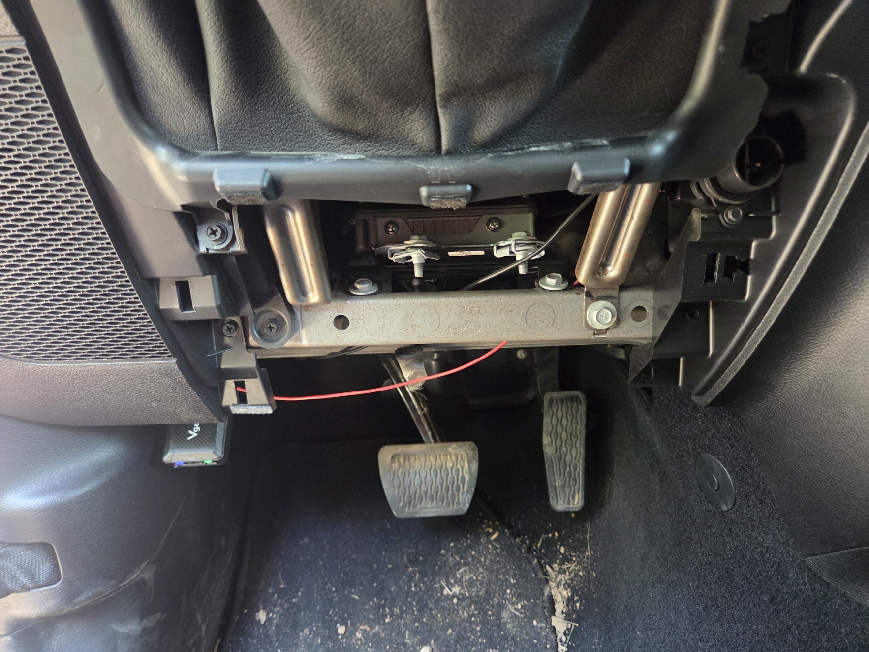
BCM Location
The Body Control Module, also called BCM or Body Computer, is located on the passenger side, behind the side panel under the glove box.
Rear Turn Signal Conversion
US specification rear lamps may use combined brake and turn signal operation. For EU specification, the rear brake lights and rear turn signals must work as separate outputs.
Configuration Changes in OBD JScan
Open the vehicle configuration/adaptation section in OBD JScan and change the following settings:
Setting |
Required Value |
Description |
|---|---|---|
Combined Rear Lighting |
Deactivated |
Disables combined brake/turn operation. The rear brake lamp remains brake-only. |
Rear Turn Lamps Output Present |
Activated |
Enables dedicated rear turn signal outputs in the BCM. |
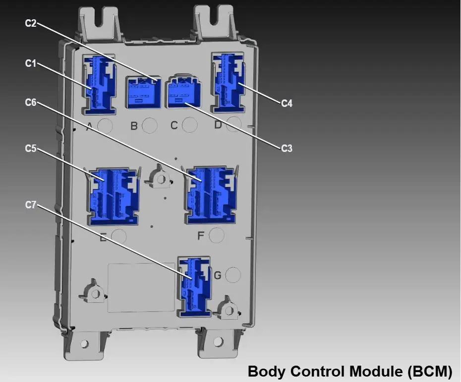
BCM Pins for Rear Turn Signals
After activating Rear Turn Lamps Output Present, the BCM outputs for the
rear turn signals become available on the following pins:
BCM Connector |
Pin |
Function |
|---|---|---|
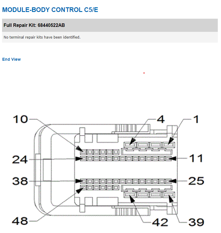
C5 / E, Black connector |
3 |
Rear turn signal output |
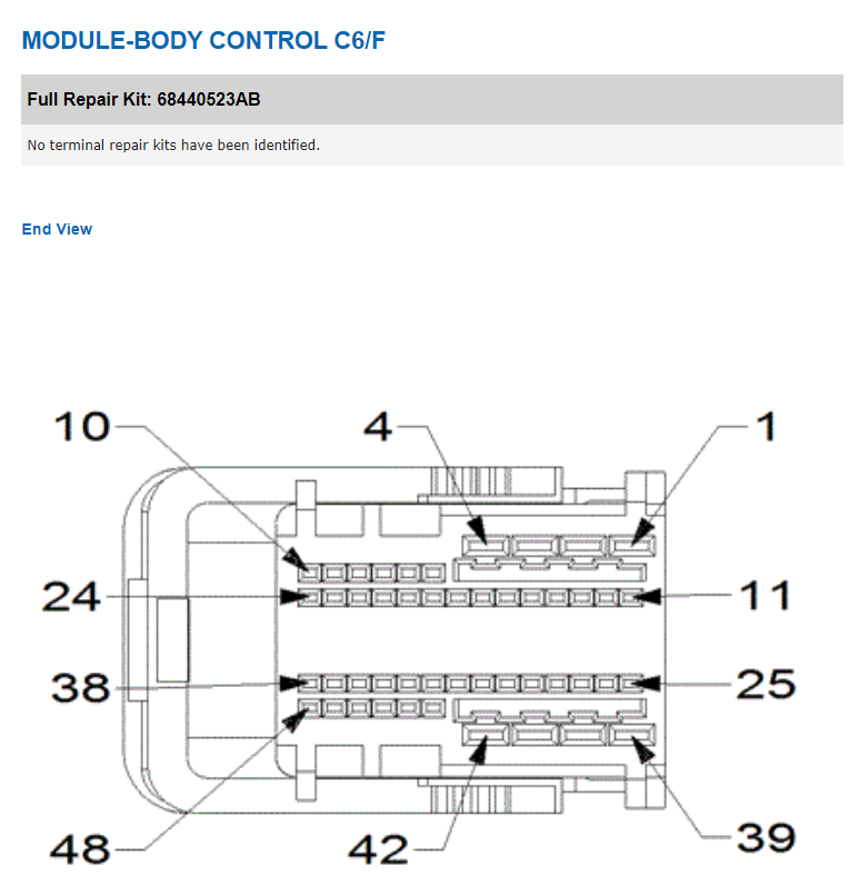
C6 / F, White connector |
42 |
Rear turn signal output |
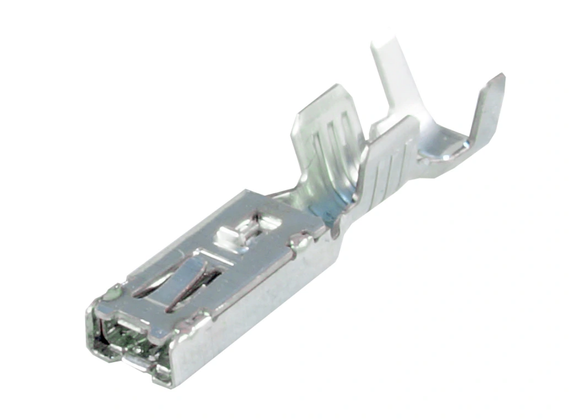
Use suitable terminals for the BCM connector.
Required terminal type:
KOSTAL 2.8 SLK
Wiring
Add two new wires from the BCM to the rear lamps:
one wire from BCM connector C5/E pin 3,
one wire from BCM connector C6/F pin 42.
Connect the new wires to the dedicated turn signal input of each EU rear lamp.
Note
The rear lamp connectors are usually the same, but the EU lamp requires an additional wire for the separate turn signal function.
Lamp Diagnostics and LED Configuration
After installing the EU rear lamps, additional configuration may be required to remove bulb warning messages or lamp diagnostic errors.
The exact settings depend on the vehicle equipment, especially whether the vehicle has LED or non-LED rear lamps.
Typical settings to verify:
LED Rear Turn Lamps,
LED Stop Lamps,
Left Rear Turn Lamp Diagnostic Present,
Right Rear Turn Lamp Diagnostic Present,
other rear lamp diagnostic settings related to the installed lamp type.
Note
These settings are vehicle-specific. If warning messages remain after the conversion, check LED/non-LED configuration and lamp diagnostic options.
Rear Fog Lamp Conversion
EU specification vehicles normally require rear fog lamps. This requires both configuration changes and additional wiring.
Configuration Changes in OBD JScan
Enable the rear fog lamp outputs:
Setting |
Required Value |
Description |
|---|---|---|
Rear Fog Lamps Output Present |
Activated |
Enables rear fog lamp outputs in the BCM. |
BCM Pins for Rear Fog Lamps
After activating Rear Fog Lamps Output Present, the rear fog lamp outputs
are available on the following BCM pins:
BCM Connector |
Pin |
Function |
|---|---|---|
C5 / E |
39 |
Rear fog lamp output |
C6 / F |
5 |
Rear fog lamp output |
Required terminal type:
KOSTAL 1.2 MLK / SLK
Wiring
Add the required wires from the BCM to the rear fog lamp circuit:
BCM connector C5/E pin 39,
BCM connector C6/F pin 5.
Connect the wires to the rear fog lamp circuit according to the vehicle wiring diagram and the installed EU rear lamp type.
Light Switch
To operate the rear fog lamps, replace the light switch with an EU specification version that includes rear fog lamp control.
Final Verification
After completing the coding and wiring work:
Cycle the ignition off and on.
Check rear brake lights.
Check left and right rear turn signals.
Check hazard lights.
Check rear fog lamps.
Check for bulb warnings on the instrument cluster.
Scan all modules for DTCs.
Correct LED/non-LED and diagnostic settings if warning messages remain.
Troubleshooting
Rear turn signals do not work
Check the following:
Rear Turn Lamps Output Presentis set toActivated.Combined Rear Lightingis set toDeactivated.The new wires are installed in the correct BCM pins.
BCM terminals are fully seated in the connector.
EU rear lamps are connected correctly.
LED/non-LED settings match the installed lamps.
Brake lights work together with turn signals
Check that Combined Rear Lighting is set to Deactivated.
Bulb warning message is displayed
Check lamp diagnostic settings and LED/non-LED configuration. Depending on the lamp type, rear turn lamp diagnostics may need to be enabled or disabled.
Rear fog lamps do not work
Check the following:
Rear Fog Lamps Output Presentis set toActivated.The rear fog lamp wires are installed in the correct BCM pins.
The vehicle has an EU specification light switch with rear fog lamp support.
Rear fog lamp wiring and lamp ground are correct.
Summary
OBD JScan can activate the BCM outputs required for EU rear lamp conversion, but the vehicle must also be physically modified. The conversion requires correct BCM coding, additional wires, correct BCM terminals, EU rear lamps, and in the case of rear fog lamps, an EU specification light switch.

Changing TPMS thresholds
Connect to your vehicle
Open Adaptation
Open TPMS settings
Set TPMS thresholds in the following:
Light Load Inflation Pressure Front / Rear Tire: Leave at 0.
Max Load Inflation Pressure Front / Rear Tire: This value is used as the minimum pressure. Change this to your liking.
Close the car, let it sit for a few minutes, and then go for a test drive and reach minimum of 30mph then system should relearn the new settings.
If you see no change in behaviour, continue to the next step:
Reset the TPMS. Use !Restart all ecus option:
from the drop-down menu choose Tire Pressure Monitor - Power On Restart
tap GO
once procedure is complete, repeat step 5.
ESS - Engine Start/Stop System
Warning
ESS settings will not work on their own. A small hardware change si required and the warning light for ESS will remain.
To successfully disable the ESS you will need to complete both changes below:
Software settings:
Connect to your vehicle in JScan
Go to Adaptation > Auto Stop/Start (ESS) Settings and see the following:
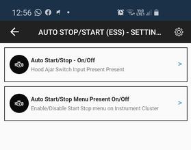
Auto Start/Stop On/Off - disable this setting to stop the ECU from monitoring the Hood Ajar switch.
Note
This will also disable Remote Start feature.
Auto Start/Stop Menu Present On/Off - disable this setting to remove the ESS-related menu entries on your instrument cluster (dashboard).
Note
If you don’t want to disable ESS but want to explore any issues with the system, enable this option - it will give you quite a good overview of the system status.
Disconnect JScan
Turn the vehicle OFF
Hardware mod:
Open the hood and follow the instructions below to disengage the Hood Ajar sensor:
The sensors (two of them) are basically simple switches. Located just next to the grille on the left side of the vehicle (on your right, when you stand in front and look at the hood).
You need to remove only one of the sensors, but leave it plugged in to the harness
On the top side of the sensor, there are two tabs in the ring that mount the sensor to the metal bracket. Press both of them to release the sensor.
Pull the sensor up
Gently pry the plastic tab that holds the sensor together to disconnect the top part
Pull the cable along with the lower part through the metal bracket opening
Reassemble the sensor and secure it below & behind the bracket in an extended position (do not squeeze it - you want to simulate the hood open state)
Tire size - Manual transmission
When changing tire size in a JL with a manual transmission it is necessary to follow the procedure below to avoid DTC P08A6 error.
Restart the PCM (Power Control Module) by either disconnecting the battery (batteries) or using JScan !Restart all ECUs adaptation
- Once reset, drive the Jeep so:
Vehicle speed is 40-80mph, in 6th gear
Accelerator pedal position is more than 0.392 volts
Flywheel torque is >75 Nm
Drive like this for at least 20 seconds.
Once the module reads all the data it will re-enable the all gear sensor performance diagnostic.
Axle ratio - Manual transmission
After changing the axle ratio on a JL with a manual transmission you may need to run the PCM - clutch replacement eeprom reset procedure to prevent the vehicle from entering the limp mode.
Adding dedicated LED DRLs (also to JL Sport)
If you have a Rubicon or Sahara:
Factory fenders have dedicated DRL wires. You need to activate both the outputs for them to work correctly. Also you need to remember that factory DRL are LED.
Required adaptations to change:
Activate: - Left Dedicated DRL Output Present - Right Dedicated DRL Output Present - Day Time Running Lights Present - LED Dedicated DRL Present - DRL Customer Setting - Daytime Running Lights Customer Settings (radio)
Set: - DRL Lamp Location - Dedicated - DRL Configuration- Canada or Europe
The Sport version of JL doesn’t have the DRL wiring in the fenders. The DRL output wires reach the connector to which the fender harness is plugged in, but the fender harness itself doesn’t have the DRL wires, so you will need to add the required wires.
LED lights / indicators warning
The best results are achieved when doing the changes in the following order:
Go to Adaptation
Navigate to the LED settings group
DISABLE “LED xyz Present On/Off” for the type of lights you want to convert to LED if you changed it already
Disable the corresponding diagnostics options.
Run !Restart All ECUs (PowerOn Restart)
Cycle the ignition (turn the Jeep off, wait a few seconds, turn it on to RUN again)
Re-connect if necessary
Enable “LED xyz Present On/Off” for the type of lights you want to convert to LED
Note
By default JL is equipped in LED diagnostic options and you need to disable it first before activating LED options. LED diagnostics are only checked when you turn on LED options
Enable Front Fog Lights with High Beam
This procedure allows the front fog lights to remain ON when high beam headlights are activated in Jeep Wrangler vehicles.
From factory configuration, fog lights automatically turn OFF when high beams are enabled. Using JScan, this behavior can be modified through the Body Module (BCM).
Procedure
Turn ignition to RUN (engine OFF).
Connect JScan to the vehicle.
Open the Body Module (BCM) module.
Navigate to Configuration.
Search for the setting related to fog light behavior with high beams (e.g. Fron Fog Lamp Dropout Enable or similar wording).
Change the setting to Disabled (or equivalent option allowing fog lights to stay ON).
Confirm and write the configuration to the vehicle.
After Completion
Turn ignition OFF.
Wait at least 30 seconds.
Turn ignition back to RUN.
Verify that fog lights remain ON when high beams are activated.
Clear any stored Diagnostic Trouble Codes (DTCs) if necessary.
Important Notes
This modification changes factory lighting behavior.
Ensure compliance with local road regulations before enabling this feature.
Some regional configurations may use slightly different naming for the setting.
Enabling auto high beam option on Jeep JL / JT
Note
this REQUIRES you have the forward facing module up center of the windshield, in the area of the inside rear view mirror. This contains the DASM. It’s the radar and camera that handles ACC, Forward Collision Warning, etc.
This option may not work on early 2019 JL models - software update at the dealer may be required.
If you do not have that black box up there, you cannot enable auto high beams.
Go to Adaptations and open group “Auto Headlamp & Auto High Beam”
Auto High Beam -> Activated it will activate this option
Auto High Beam Module Location -> Select IRCM - this tells ecu where the module is installed
Auto High Beam On Threshold -> 25 km/h - this is default on some cars, on others it is 0 and in booth cases it should work.
Auto High Beam Off Threshold -> 20 km/h - this is default on some cars, on others it is 0 and in booth cases it should work.
Auto High Beam CSM Present-> Activated Radio settings screen under “Lights”, adds the menu selection so you can turn it on or off
Jeep JL/JT/4XE front “Off Road” Factory Camera install with CVPM module
Off Road Capable -> Activated
Off Road Camera Present -> Activated
Rear Camera Present -> Deactivated
Reversible Washer Pump Enable -> Activated
Connector A Pin 14 - Washer Motor Control Right -> Active
Rear View Camera Gridlines On/Off - Deactivated
Rear Camera Customer Settings Menu on Radio On/Off - Deactivated
Auto Launch Forward Facing Camera Off Road Plus CSM Present -> Deactivated
Auto Launch Off Road Plus Customer Settings Menu -> Activated
Forward Facing Camera Grid Lines Customer Settings Menu Enable/Disable -> Active
Rear CVPM Camera Dynamic Gridlines - Customer Settings Menu Enable/Disable -> Active
Rear CVPM Camera Static - Customer Settings Menu Enable/Disable -> Active
CVPM Module -> Active
Off-Road Pages Activation in Jeep Wrangler JL/JT Using JScan
What You’ll Need: Radio 8.4 other versions don’t have Off-Road pages A compatible OBD2 adapter with CAN-MS access (e.g., vLinker MC+,vLinker MS, OBDLink MX+, ). SGW Bypass module (Security Gateway Bypass) – required for making changes and ensuring proper functionality.
Connect to Your Vehicle
In the JScan app, go to Adaptations or Body Module - Configuration. Look for the Off-Road Pages option
Enable Off-Road Pages
Change the Off-Road Pages setting to Enabled. Save the changes and follow any on-screen instructions.
Restart the Uconnect System (Radio Restart via JScan)
After enabling Off-Road Pages, you must perform two (2x) Uconnect (radio) restarts using the JScan app. This restart function is only available when using an OBD2 adapter with CAN-MS access. Navigate to Adaptations -> Vehicle Maintance in JScan and select !Restart -> find Radio and run restart twice. Full System Reboot (if necessary)
If Off-Road Pages do not appear after the JScan restarts, try disconnecting the battery for a few minutes or performing a hard reset of Uconnect. Verify Activation
Once the system reboots, check if the Off-Road Pages tab appears in the Uconnect menu.
Important Notes:
Jeep Wrangler JL has a built-in Security Gateway (SGW) that blocks unauthorized changes, so you must install an SGW Bypass module before making any modifications. The SGW Bypass must remain installed for Off-Road Pages to function correctly after activation. The JScan radio restart feature is only available with an OBD2 adapter that supports CAN-MS. Without CAN-MS access, you will need to manually restart Uconnect (by disconnecting the battery). Some Uconnect versions may require additional coding or software updates. Ensure you have the latest version of JScan and a compatible OBD2 adapter. If Off-Road Pages do not appear, try re-saving the settings and performing another radio/system restart. Now you’re all set to enjoy the Off-Road Pages feature in your Jeep Wrangler JL! 🚙💨
Jeep JL LED Tail Lamp settings JScan
Note
This is general guide, it may be slightly different for your car
Basically there are 2 types of aftermarket LED lights
with resistor – those type of lamps will act like standard bulb lamps
without resistor – those type of lamps will act like factory led but without diagnostic
All changes should be done in: Body -> Configuration
- With resistor
LED Rear Turn Lamps Present -> “Not Set”
LED Reverse Lamps Present -> “Not Set”
LED Stop Lamps Present -> “Not Set”
LED Tail Lamps Present -> “Not Set”
Left Rear Turn Lamp Diagnostic Present -> “Not Set”
Right Rear Turn Lamp Diagnostic Present -> “Not Set”
- Without resistor:
LED Rear Turn Lamps Present -> “Set”
LED Reverse Lamps Present -> “Set”
LED Stop Lamps Present -> “Set”
LED Tail Lamps Present -> “Set”
Left Rear Turn Lamp Diagnostic Present -> “Not Set”
Right Rear Turn Lamp Diagnostic Present -> “Not Set”
When you are don with settings go to Body Module and clear all trouble codes (DTC). Then lock the car and wait for power cycle (instrument cluster goes to sleep) sometimes it may be required 2x Then you can start testing, it’s important to test with engine started. You can leave OBD adapter connected all the time. All lights are managed from Body module so all codes related to instrument cluster messages are visible there
Disable Sign and Lane assist
Jeep JL disable Sign and Lane assist
Go to Modules > Body Controller > Configuration
- Set these to disabled:
Lane departure warning present
Traffic Sign Info
Transfer case swap on JL or JT
T241 (MP1622 / MP1622C)
Classic mechanical part-time transfer case (Command-Trac / Rock-Trac)
Rigid front–rear connection (no center differential, no clutch)
Modes: 2H / 4H / N / 4L, no AUTO mode
4WD use only on loose/slippery surfaces (snow, mud, off-road)
Available with low range ratio: 2.72:1 or 4:1 (Rock-Trac)
T246 (MP3022 / MP3022C)
Active on-demand 4WD system (Selec-Trac) with multi-plate clutch
Automatic torque distribution (4H Auto) with part-time lock capability
Modes: 2H / 4H Auto / 4H Part-Time / N / 4L
Suitable for all surfaces, including dry pavement
Available with low range ratio: 2.72:1 or 4:1 (Rock-Trac)
Go to Modules > Body Controller > Configuration
- Select correct transfer case type:
T241 - (MP1622/MP1622C)
T246 - (MP3022/MP3022C)
Important Notes
This is only part of the transfer case swap process. You will also need to perform the necessary mechanical modifications, including: - Installing the new transfer case - Replacing Drive Train Contol Module (DTCM) located on ther back of the car - Replacing the transfer shift leaver and add missing wires to the harness
Disable Electric Power Steering (EPS) – Jeep Wrangler JL / JT
This procedure allows deactivation of the factory Electric Power Steering (EPS) system in Jeep Wrangler JL and Jeep Gladiator JT vehicles.
This is typically required when:
Converting from factory Electric Power Steering to a hydraulic steering system (e.g. PSC hydraulic pump installation)
Performing engine swaps (e.g. 5.7L HEMI or 6.4L HEMI conversions)
Installing aftermarket steering systems that do not use the OEM EPS module
Procedure
Turn ignition to RUN (engine OFF).
Connect JScan to the vehicle.
Open the Body module.
Navigate to Configuration.
Search for EPS (Electric Power Steering).
Set value to Not Set.
Confirm and write the configuration to the vehicle.
After Completion
Turn ignition OFF.
Wait at least 30 seconds.
Turn ignition back to RUN.
Clear any stored Diagnostic Trouble Codes (DTCs).
Verify that no EPS-related warnings remain active.
Important Notes
Setting EPS to Not Set disables factory electric steering assist.
A properly installed hydraulic steering system must be present before driving.
Intended for custom/off-road applications only.
Always ensure compliance with local regulations before modifying steering systems.
2025 tire size change FFCM calibration issue
After changing the tire size on a late 2025 you may run into an FFCM calibration issue. This is a module software bug, and has been recognised by Jeep.
Please see this Technical Service Bulletin (TSB) and contact the dealer.
Activating Front Camera (CHML) on 2018+
Adding a forward-facing trail camera to your Jeep Wrangler JL (model years 2018+) can greatly aid in off-road navigation and tight parking situations. Fortunately, all Wrangler JLs equipped with the 8.4-inch Uconnect infotainment system (Panasonic radio) have a built-in provision for an auxiliary video input, originally intended for a cargo or CHMSL camera (typically used on truck bed or third brake light cameras). Any NTSC camera is compatible with this setup, just get one with a wide-angle lens for the best view, also check if this camera has option to mirror the image if needed.
Go to Modules > Body Controller > Configuration
- Set these to active:
CHML Camera Present or Cargo Camera Present
Restart the Radio using JScan 2x - this is required for the settings to take effect.
- Wire the Camera in to radio connectors:
2018/2019 - pin 24, black in 25
2020+ - pin 21, black in 22
Warning
Some late 2019 models have different pinouts, please check before wiring.

Driver Assistance System Module (DASM) calibration
Note
Applies to RAM DT, Wrangler JL, Gladiator JT, Wrangler 4xe, and possibly additional models.
DASM Auto Alignment procedure is used to recalibrate the Driver Assistance System Module (DASM) after replacement, windshield change, tire diameter alteration, or when certain fault codes appear.
This prcedure runs the auto- alignment process for the DASM, ensuring it is correctly calibrated for optimal performance. Procedure has to complete booth steeps without interruption.
If the DASM is not properly aligned, it may lead to incorrect operation of driver assistance features, such as adaptive cruise control, lane- keeping assist, and automatic emergency braking.
If you can’t complete the procedure, you can manually adjust the DASM angle using the steps below.
Introduction
The Driver Assistance System Module (DASM) needs recalibration if it has been replaced, the windshield was changed, tire diameter was altered, or if certain fault codes appear. The main step is adjusting the module’s angle with the screw.
How to Adjust the Screw
Measure the angle
Place a digital inclinometer against the cooling ribs on the back of the DASM.
Record the vertical angle.
Adjust the screw
Use an E5 Torx tool on the adjustment head screw (marked “1” in the diagram).
Turn in small increments to move the module angle.
After each adjustment, remove the tool and recheck the angle with the inclinometer.
Target specification
The DASM must be set at - 1° ±0.2° from vertical (ideal: - 1° ±0.1°).
Repeat until correct
Measure → adjust screw → remeasure, until the angle is within specification.
Finalize calibration
Run procedure DASM Auto Alignment.
Follow on- screen instructions to complete calibration.
115V to 230V Power Inverter Conversion JL/JT/4XE and more
This procedure describes the replacement of the factory US-specification 115V AC power inverter with the European 230V AC version.
The US and EU inverters use the same electrical connectors and mounting points. No BCM, PCM, or vehicle configuration changes are required.
Note
This is a hardware-only modification. No coding or programming is required.
Overview
Vehicles equipped with a factory AC power outlet use a dedicated inverter module that converts vehicle DC voltage into AC power.
US specification vehicles are equipped with a 115V inverter, while European vehicles use a 230V inverter.
To obtain a functional 230V outlet, the US inverter must be replaced with the corresponding European version.
Connector Modification
The vehicle-side connector may require a minor modification before it can be connected to the European inverter.
The side plastic guides on the vehicle harness connector may prevent proper engagement with the inverter connector. If necessary, carefully trim or file the side plastic tabs until the connector can be fully inserted and locked into place.
Warning
Remove only the minimum amount of material required for proper fitment. Excessive trimming may affect connector retention and locking performance.
After modification, verify that:
the connector is fully seated,
the locking tab engages correctly,
the connector cannot be removed without releasing the lock,
no terminals, seals, or wires have been damaged.
Note
This modification affects only the plastic housing of the vehicle-side connector. No wiring changes, terminal replacements, or vehicle coding are required.
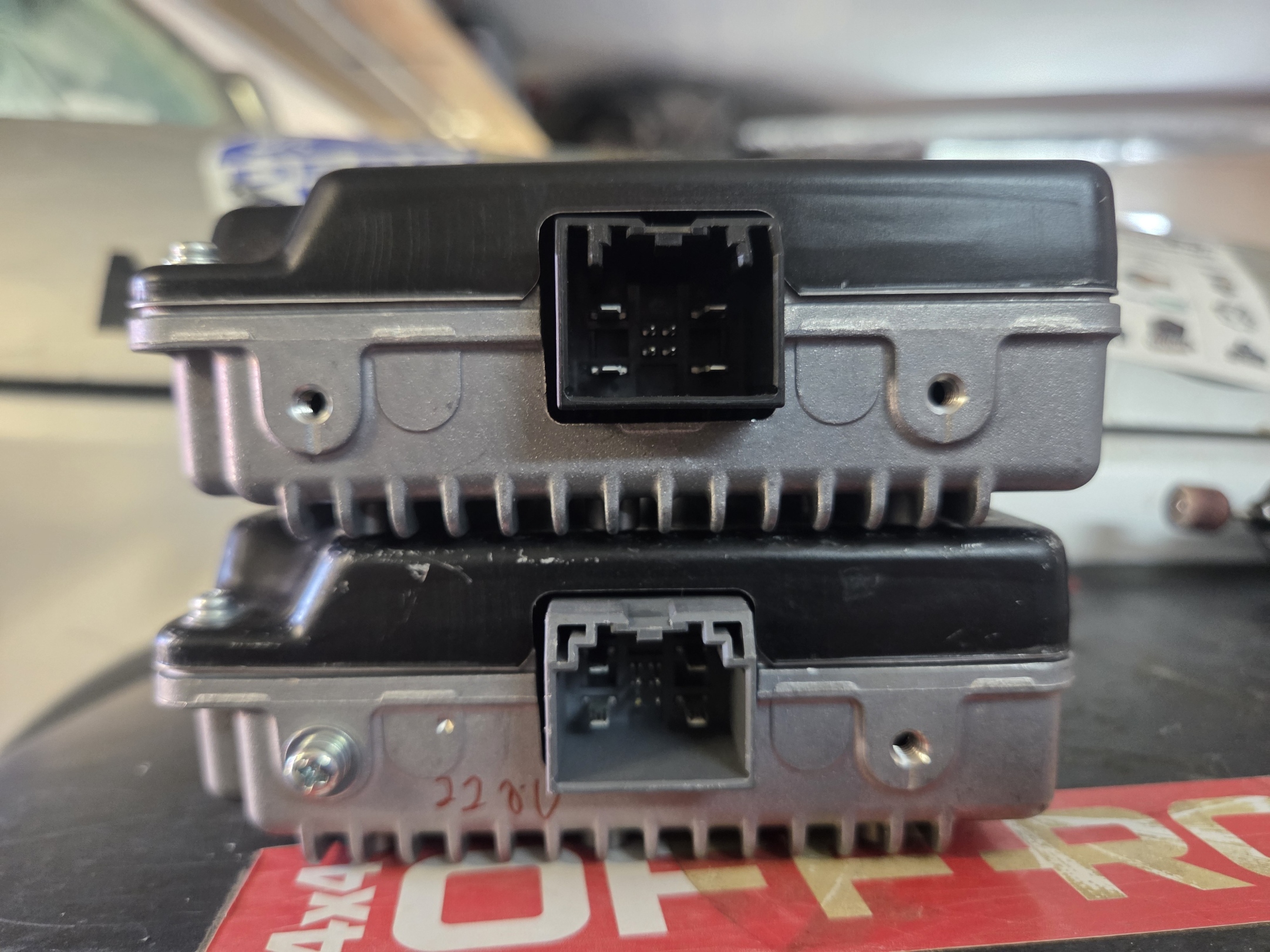
Required Parts
Select the inverter according to the vehicle model year.
Power Inverter
Model Years |
Part Number |
Description |
|---|---|---|
2018-2021 |
68349353AA |
230V AC power inverter |
2022+ |
68454720AB |
230V AC power inverter |
Rear AC Outlet
If required, install the European AC outlet assembly:
Part Number |
Description |
|---|---|
68347435AA |
Rear console AC outlet assembly |
Note
The electrical connectors are identical between US and EU versions. Only the inverter and outlet hardware differ.
Inverter Location
The inverter module is located behind the dashboard, near the instrument cluster and steering column area.
Access to the inverter typically requires removal of dashboard trim panels.
Typical inverter location behind the dashboard near the steering column.
Typical inverter location behind the dashboard near the steering column.
Replacement Procedure
Turn the ignition off.
Disconnect the negative battery terminal.
Remove the required dashboard trim panels.
Locate the inverter module.
Disconnect all electrical connectors.
Remove the inverter mounting fasteners.
Remove the US-specification inverter.
Install the European 230V inverter.
Reconnect all electrical connectors.
Reinstall dashboard components.
Reconnect the battery.
Verification
After installation:
Start the vehicle.
Enable the AC power outlet according to the owner’s manual.
Verify that the outlet indicator operates normally.
Connect a suitable 230V device and confirm proper operation.
No Programming Required
Unlike many vehicle feature retrofits, this conversion does not require:
The vehicle automatically operates the replacement inverter through the existing wiring and control circuits.
Troubleshooting
Outlet Does Not Provide Power
Check the following:
Inverter connectors are fully seated.
The inverter matches the vehicle model year.
Vehicle battery voltage is within specification.
All inverter fuses are intact.
The outlet assembly is compatible with the installed inverter.
Outlet Provides Incorrect Voltage
Verify that a European 230V inverter has been installed. A US-specification 115V inverter will continue to output approximately 115V AC regardless of the outlet type installed.
Summary
Converting the factory AC outlet system from 115V to 230V requires only replacement of the inverter module and, if desired, the outlet assembly. The wiring, connectors, and vehicle configuration remain unchanged, and no programming or coding is required.
Gladiator JT (2018+)
General hints for JT
For ESS (and other features) please see the JL section above - JT shares a lot with the JL model.
Jeep Wrangler JL/JT 2018+ Rear Lights Conversion US to EU
This procedure describes the general steps required to convert rear lamps on Jeep Wrangler JL/JT 2018+ from US specification to EU specification.
The conversion usually includes:
separating rear brake lights from rear turn signals,
enabling dedicated rear turn signal outputs in the BCM,
adding missing wires between the BCM and rear lamps,
installing EU specification rear lamps,
enabling rear fog lamp outputs,
replacing the light switch with an EU specification version when rear fog lamps are required.
Warning
This procedure requires physical wiring modifications. OBD JScan can only change the vehicle configuration. It cannot replace missing wires, connectors, lamps, or switches.
Warning
Always verify the wiring diagram for the exact vehicle year, body type, trim level, and lamp package before modifying the vehicle wiring. Incorrect wiring may damage the BCM or lighting components.
Required Parts
Depending on the vehicle equipment and the scope of conversion, the following parts may be required:
EU specification rear lamps,
additional wires from BCM to rear lamps,
BCM terminal pins,
KOSTAL 2.8 SLK terminals for rear turn signal outputs,
KOSTAL 1.2 MLK / SLK terminals for rear fog lamp outputs,
EU specification light switch with rear fog lamp function,
suitable OBD adapter supported by OBD JScan.
BCM Location
The Body Control Module, also called BCM or Body Computer, is located on the passenger side, behind the side panel under the glove box.
Rear Turn Signal Conversion
US specification rear lamps may use combined brake and turn signal operation. For EU specification, the rear brake lights and rear turn signals must work as separate outputs.
Configuration Changes in OBD JScan
Open the vehicle configuration/adaptation section in OBD JScan and change the following settings:
Setting |
Required Value |
Description |
|---|---|---|
Combined Rear Lighting |
Deactivated |
Disables combined brake/turn operation. The rear brake lamp remains brake-only. |
Rear Turn Lamps Output Present |
Activated |
Enables dedicated rear turn signal outputs in the BCM. |
BCM Pins for Rear Turn Signals
After activating Rear Turn Lamps Output Present, the BCM outputs for the
rear turn signals become available on the following pins:
BCM Connector |
Pin |
Function |
|---|---|---|
C5 / E, Black connector |
3 |
Rear turn signal output |
C6 / F, White connector |
42 |
Rear turn signal output |
Use suitable terminals for the BCM connector.
Required terminal type:
KOSTAL 2.8 SLK
Wiring
Add two new wires from the BCM to the rear lamps:
one wire from BCM connector C5/E pin 3,
one wire from BCM connector C6/F pin 42.
Connect the new wires to the dedicated turn signal input of each EU rear lamp.
Note
The rear lamp connectors are usually the same, but the EU lamp requires an additional wire for the separate turn signal function.
Lamp Diagnostics and LED Configuration
After installing the EU rear lamps, additional configuration may be required to remove bulb warning messages or lamp diagnostic errors.
The exact settings depend on the vehicle equipment, especially whether the vehicle has LED or non-LED rear lamps.
Typical settings to verify:
LED Rear Turn Lamps,
LED Stop Lamps,
Left Rear Turn Lamp Diagnostic Present,
Right Rear Turn Lamp Diagnostic Present,
other rear lamp diagnostic settings related to the installed lamp type.
Note
These settings are vehicle-specific. If warning messages remain after the conversion, check LED/non-LED configuration and lamp diagnostic options.
Rear Fog Lamp Conversion
EU specification vehicles normally require rear fog lamps. This requires both configuration changes and additional wiring.
Configuration Changes in OBD JScan
Enable the rear fog lamp outputs:
Setting |
Required Value |
Description |
|---|---|---|
Rear Fog Lamps Output Present |
Activated |
Enables rear fog lamp outputs in the BCM. |
BCM Pins for Rear Fog Lamps
After activating Rear Fog Lamps Output Present, the rear fog lamp outputs
are available on the following BCM pins:
BCM Connector |
Pin |
Function |
|---|---|---|
C5 / E |
39 |
Rear fog lamp output |
C6 / F |
5 |
Rear fog lamp output |
Required terminal type:
KOSTAL 1.2 MLK / SLK
Wiring
Add the required wires from the BCM to the rear fog lamp circuit:
BCM connector C5/E pin 39,
BCM connector C6/F pin 5.
Connect the wires to the rear fog lamp circuit according to the vehicle wiring diagram and the installed EU rear lamp type.
Light Switch
To operate the rear fog lamps, replace the light switch with an EU specification version that includes rear fog lamp control.
Final Verification
After completing the coding and wiring work:
Cycle the ignition off and on.
Check rear brake lights.
Check left and right rear turn signals.
Check hazard lights.
Check rear fog lamps.
Check for bulb warnings on the instrument cluster.
Scan all modules for DTCs.
Correct LED/non-LED and diagnostic settings if warning messages remain.
Troubleshooting
Rear turn signals do not work
Check the following:
Rear Turn Lamps Output Presentis set toActivated.Combined Rear Lightingis set toDeactivated.The new wires are installed in the correct BCM pins.
BCM terminals are fully seated in the connector.
EU rear lamps are connected correctly.
LED/non-LED settings match the installed lamps.
Brake lights work together with turn signals
Check that Combined Rear Lighting is set to Deactivated.
Bulb warning message is displayed
Check lamp diagnostic settings and LED/non-LED configuration. Depending on the lamp type, rear turn lamp diagnostics may need to be enabled or disabled.
Rear fog lamps do not work
Check the following:
Rear Fog Lamps Output Presentis set toActivated.The rear fog lamp wires are installed in the correct BCM pins.
The vehicle has an EU specification light switch with rear fog lamp support.
Rear fog lamp wiring and lamp ground are correct.
Summary
OBD JScan can activate the BCM outputs required for EU rear lamp conversion, but the vehicle must also be physically modified. The conversion requires correct BCM coding, additional wires, correct BCM terminals, EU rear lamps, and in the case of rear fog lamps, an EU specification light switch.
Changing TPMS thresholds
Connect to your vehicle
Open Adaptation
Open TPMS settings
Set TPMS thresholds in the following:
Light Load Inflation Pressure Front / Rear Tire: Leave at 0.
Max Load Inflation Pressure Front / Rear Tire: This value is used as the minimum pressure. Change this to your liking.
Close the car, let it sit for a few minutes, and then go for a test drive and reach minimum of 30mph then system should relearn the new settings.
If you see no change in behaviour, continue to the next step:
Reset the TPMS. Use !Restart all ecus option:
from the drop-down menu choose Tire Pressure Monitor - Power On Restart
tap GO
once procedure is complete, repeat step 5.
Bed Power Outlet Install
See the Bed Power Outlet installation video (this is not our resource) for a full guide. JScan usage for settings is shown around 8:48 (linked)
Driver Assistance System Module (DASM) calibration
Note
Applies to RAM DT, Wrangler JL, Gladiator JT, Wrangler 4xe, and possibly additional models.
DASM Auto Alignment procedure is used to recalibrate the Driver Assistance System Module (DASM) after replacement, windshield change, tire diameter alteration, or when certain fault codes appear.
This prcedure runs the auto- alignment process for the DASM, ensuring it is correctly calibrated for optimal performance. Procedure has to complete booth steeps without interruption.
If the DASM is not properly aligned, it may lead to incorrect operation of driver assistance features, such as adaptive cruise control, lane- keeping assist, and automatic emergency braking.
If you can’t complete the procedure, you can manually adjust the DASM angle using the steps below.
Introduction
The Driver Assistance System Module (DASM) needs recalibration if it has been replaced, the windshield was changed, tire diameter was altered, or if certain fault codes appear. The main step is adjusting the module’s angle with the screw.
How to Adjust the Screw
Measure the angle
Place a digital inclinometer against the cooling ribs on the back of the DASM.
Record the vertical angle.
Adjust the screw
Use an E5 Torx tool on the adjustment head screw (marked “1” in the diagram).
Turn in small increments to move the module angle.
After each adjustment, remove the tool and recheck the angle with the inclinometer.
Target specification
The DASM must be set at - 1° ±0.2° from vertical (ideal: - 1° ±0.1°).
Repeat until correct
Measure → adjust screw → remeasure, until the angle is within specification.
Finalize calibration
Run procedure DASM Auto Alignment.
Follow on- screen instructions to complete calibration.
115V to 230V Power Inverter Conversion JL/JT/4XE and more
This procedure describes the replacement of the factory US-specification 115V AC power inverter with the European 230V AC version.
The US and EU inverters use the same electrical connectors and mounting points. No BCM, PCM, or vehicle configuration changes are required.
Note
This is a hardware-only modification. No coding or programming is required.
Overview
Vehicles equipped with a factory AC power outlet use a dedicated inverter module that converts vehicle DC voltage into AC power.
US specification vehicles are equipped with a 115V inverter, while European vehicles use a 230V inverter.
To obtain a functional 230V outlet, the US inverter must be replaced with the corresponding European version.
Connector Modification
The vehicle-side connector may require a minor modification before it can be connected to the European inverter.
The side plastic guides on the vehicle harness connector may prevent proper engagement with the inverter connector. If necessary, carefully trim or file the side plastic tabs until the connector can be fully inserted and locked into place.
Warning
Remove only the minimum amount of material required for proper fitment. Excessive trimming may affect connector retention and locking performance.
After modification, verify that:
the connector is fully seated,
the locking tab engages correctly,
the connector cannot be removed without releasing the lock,
no terminals, seals, or wires have been damaged.
Note
This modification affects only the plastic housing of the vehicle-side connector. No wiring changes, terminal replacements, or vehicle coding are required.
Required Parts
Select the inverter according to the vehicle model year.
Power Inverter
Model Years |
Part Number |
Description |
|---|---|---|
2018-2021 |
68349353AA |
230V AC power inverter |
2022+ |
68454720AB |
230V AC power inverter |
Rear AC Outlet
If required, install the European AC outlet assembly:
Part Number |
Description |
|---|---|
68347435AA |
Rear console AC outlet assembly |
Note
The electrical connectors are identical between US and EU versions. Only the inverter and outlet hardware differ.
Inverter Location
The inverter module is located behind the dashboard, near the instrument cluster and steering column area.
Access to the inverter typically requires removal of dashboard trim panels.
Typical inverter location behind the dashboard near the steering column.
Typical inverter location behind the dashboard near the steering column.
Replacement Procedure
Turn the ignition off.
Disconnect the negative battery terminal.
Remove the required dashboard trim panels.
Locate the inverter module.
Disconnect all electrical connectors.
Remove the inverter mounting fasteners.
Remove the US-specification inverter.
Install the European 230V inverter.
Reconnect all electrical connectors.
Reinstall dashboard components.
Reconnect the battery.
Verification
After installation:
Start the vehicle.
Enable the AC power outlet according to the owner’s manual.
Verify that the outlet indicator operates normally.
Connect a suitable 230V device and confirm proper operation.
No Programming Required
Unlike many vehicle feature retrofits, this conversion does not require:
The vehicle automatically operates the replacement inverter through the existing wiring and control circuits.
Troubleshooting
Outlet Does Not Provide Power
Check the following:
Inverter connectors are fully seated.
The inverter matches the vehicle model year.
Vehicle battery voltage is within specification.
All inverter fuses are intact.
The outlet assembly is compatible with the installed inverter.
Outlet Provides Incorrect Voltage
Verify that a European 230V inverter has been installed. A US-specification 115V inverter will continue to output approximately 115V AC regardless of the outlet type installed.
Summary
Converting the factory AC outlet system from 115V to 230V requires only replacement of the inverter module and, if desired, the outlet assembly. The wiring, connectors, and vehicle configuration remain unchanged, and no programming or coding is required.
Grand Cherokee (WK/WK2)
Choosing the correct adapter
For WK2 2014+ an MS-CAN capable OBD adapter is required for full compatibility. See Choosing the right adapter in JL/JT section.
Bypassing the Security Gateway
Chrysler’s Secure Gateway Module came out in 2018. The SGW is a module whose function is simply to keep the communication networks secure. The SGW protects the vehicle networks from being exploited by creating a firewall between two portions of the network with the most vulnerability. This means, that to make any changes, you will need a SGW bypass - usually a cable. See our SGW Bypass page for details.
Tire Size
Note
In models equipped with the advanced Park Sense module (not the basic, 4-sensor one) setting a bigger tire size will cause Park Sense and ABS errors and there is currently no known solution.
Generally, follow the default Tire Size procedure, and then:
if everything works fine after you restart the car, you’re good to go
- if you are getting an ABS error:
Run ABS Initialization adaptation
Run Advanced Scan and clear the error codes
Cycle the ignition (shut the car down, wait a moment, start it again)
SRT Mode vs Performance Pages
If you want to enable SRT / Performance Pages on the radio, don’t use SRT Mode Adaptation. This adaptation is used if you actually have an SRT hardware. To enable SRT options on the radio use Performance Pages adaptation, and be aware that the radio might need up to 24 hrs to catch up on changes made and/or a hard reset (pulling the radio fuse) if 24 hrs wait is not enough.
How to: Convert rear lamps on Grand Cherokee < 2014 from US to EU spec
Note
This description is based on Wrangler JK process and might not be accurate. Inspect your vehicle wiring, diagrams and consult with someone who has some experience already. If the description is inaccurate, please reach out to us. Your feedback is highly appreciated.
Replace US rear lights with EU version
Set Combined Rear Lightning On/Off -> Set this option to Deactivated. This will leave only turn signals instead of combined lamps.
You will now need to add a wire from the third (center) stop light to the stop lights on the sides.
How to: Convert rear lamps on Grand Cherokee 2014-2020 from US to EU spec
General steps required to convert car to euro spec
Steps required to enable rear turn signals
Combined Rear Lightning On/Off -> Set this option to Deactivated – this option will disable, brake with turn, only brake light will be available.
- Check if Rear Turn Lamps Output Present -> Activated – this option will enable large pins C5/E pin number 3 & C6/F pin number 42 on BCM (Body Computer).
Note
In most vehicles the wiring harness will already have those pins properly wired. If the conversion doesn’t work as expected, check the wiring first.
Right – Second Reverse Lamp – On/Off -> Set this option to Deactivated
Left – Second Reverse Lamp – On/Off -> Set this option to Deactivated
Replace white reverse bulbs with orange bulbs and conversion is completed
BCM diagram:
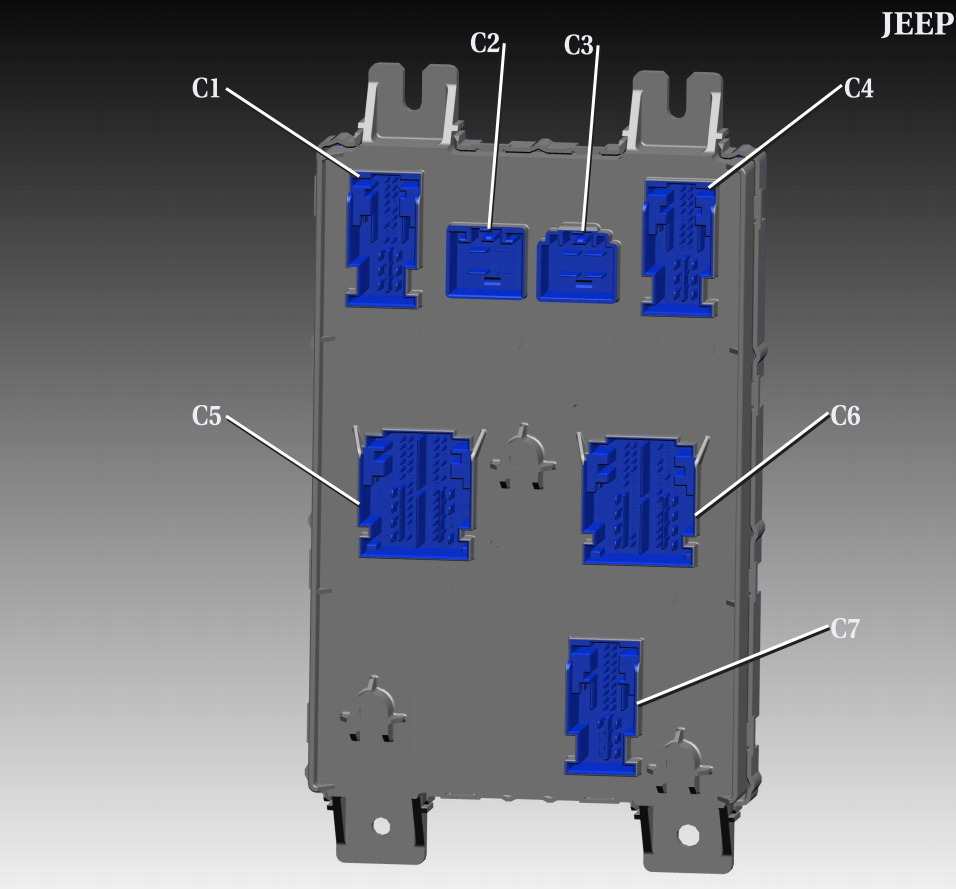
Plug / connector layouts:
Steps required to enable rear fog lights
Rear Fog Lamps Output Present -> Activated – This option will activate two new pins on BCM C5/E pin number 39 & C6/F pin number 5:
Small pins “KOSTAL 1,2 MLK”
Right – Rear Fog Lamp or High Beam Shutter On/Off -> Set to Activated
Left – Rear Fog Lamp or High Beam Shutter On/Off -> Set to Activated
Add wires to BCM C5/E pin number 39 & C6/F pin number 5
Connect wires to new rear fog lights
Fog lamp button should now work with double press
Air Suspension - Calibration
Vehicle height is to be checked with the vehicle on a flat, level surface, preferably a vehicle alignment rack. The tires are to be inflated to the recommended pressure. All tires are to be the same size as standard equipment. Vehicle height is checked with the fuel tank full of fuel, and no passenger or luggage compartment load.
HEIGHT MEASUREMENT - all values need to be measuered and enterd in milimiters “mm”
Front:
Front Wheel Center Height – Measure the vertical distance between the front wheel center (1) and the ground (4), Record the measurement. 2. Front Cradle Height – Measure the vertical distance between the center of the cradle bolt (2) to the ground (3), Record the measurement. 3. Take the two measurements and subtract them to get the ride height.

Rear:
Rear Wheel Center Height – Measure the vertical distance between the wheel center (2) and the ground (3), Record the measurement. 5. Rear Cradle Height – Measure the vertical distance between the center of the cradle bolt (1) to the ground (4), Record the measurement. 6. Take the two measurements and subtract them to get the ride height.

Reference Table:

Air Suspension (to be completed)
Key notes:
DO NOT use the Leveling procedure instead of the terrain selector, as it puts the suspension in service mode.
Anything below 50mm for the rear will make the pump keep running forever.
Factory: WK2 - Trailhawk 2020
Front Left = 90mm
Front Right = 89mm
Rear Left = 65mm
Rear Right - 67mm
Lowered: WK2
Front Left = 75mm
Front Right = 74mm
Rear Left = 50mm
Rear Right - 52mm
The adjustment of the ride height can change the Normal Ride Height (NRH). The values of different modes (example below) cannot be changed.
For example, for 2011 the basics of how the different automatic settings effect the systems are listed below:
Auto - When in 4WD High range the vehicle height is at NRH. The vehicle systems are set to normal performance settings. Combines optimal traction with seamless steering feel. When in 4WD Low range the vehicle height adjusts to 38 mm (1.49 in.) above NRH, the transfer case locks, and the transmission shifting adjusts to off road shifting.
Sport - When in 4WD High range the vehicle height adjusts to 15 mm (0.59 in.) below NRH. Electronic Stability Control (ESC) and traction control tuning thresholds are raised, and the Antilock Brake Control (ABS) allows less wheel slip, all to allow more driver control. Also the transmission shifting adjusts to a higher performance shifting. Not available in 4WD Low range .
Snow - When in 4WD High range the vehicle height is at NRH. Traction control is adjusted to allow less wheel slip, and initial vehicle launch will be in second gear. When in 4WD Low range the vehicle height adjusts to 33 mm (1.3 in.) above NRH, the transfer case locks, the transmission shifting and ABS adjusts to off road settings.
Sand/Mud - When in 4WD High range the vehicle height adjusts to 38 mm (1.49 in.) above NRH. Electronic Stability Control (ESC) tuning threshold is raised, and the ABS allows less wheel slip to allow more driver control. When in 4WD Low range the vehicle height adjusts to 38 mm (1.49 in.) above NRH. The transfer case and the Electronic Limited Slip Differential (ELSD) locks, the transmission shifting and ABS adjusts to off road settings.
Rock - Not available in 4WD High range . When in 4WD Low range the vehicle height adjusts to 65 mm (2.6 in.) above NRH. The transfer case and the ELSD locks, the transmission shifting and ABS adjusts to off road settings, and hill descent control is activated for steep downhill control.
Air suspension delete
Note
For pre-lift (up to 2014) models:
If you’re removing the air suspnesion and replacing it with regular coilovers, follow the steps below (as always: it is YOUR responsibility and we take no liability for any damages)
Eemove the 2 fuses related to the air suspension and also the relay located in the relay box beside de fuse panel
Disable the air suspension module control with Jscan.
Adaptation > Modules Configuration > ASCM - Air Suspension Control On/Off > set to Deactivated
Unhook the module itself located under the driver seat.
Disconnect the negative terminal of the main battery for 30 seconds and reconnect it to get rid of the message and the blinking buttons.
If you get ABS errors, run ABS initialization procedure.
WK2 - 2014+ - HID Lamps configuration
High Intensity Discharge Head Lamps -> Set
Low Beam Output or Low Beam Output Present -> Not Set (This param may not exist on some models)
Bi-Xenon Headlamps -> Set
LED Front Turn Lamps -> Set
LED Dedicated DRL -> Set
LED Front Park / Marker Lamps -> Set
Left High Beam Voltage -> 13.0 Volts
Right High Beam Voltage -> 13.0 Volts
IOD RELAY OFF HSD Present / Relay OFF High Side Down Present -> Set
IOD RELAY ON HSD Present / Relay ON High Side Down Present -> Set
Ignition-OffDraw (IOD) OFF HSD output -> Set (This param may not exist on some models)
Ignition-Off Draw (IOD) ON HSD output -> Set (This param may not exist on some models)
IOD RELAY ON HSD Usage Left HID Lamp -> WK (This param may not exist on some models)
IOD RELAY OFF HSD Usage -> Right HID Lamp - WK (This param may not exist on some models)
Right Dedicated DRL Output -> Set
Left Dedicated DRL Output -> Set
DRL Lamps Location -> Dedicated
DRL Dropout -> Set
Left DRL Voltage -> 7.4 Volts
Right DRL Voltage -> 7.4 Volts
Front Driver Door Ajar Switch Signal Usage -> Left Front La Diagnostics (Jeep/RAM)
Front Passenger Door Ajar Switch Signal Usage -> Right Front Lamp Diagnostics (Jeep/RAM)
If it still dosen’t work search for params related to HSD
Remote Start Enable
Note
For pre-lift (up to 2014) models
Module: Front Control Module (FCM) Configuration - Remote Start Present → SET - Reconfig Input 2 (B11) → Hood Ajar - (Important: the hood ajar sensor must use a 1 kΩ resistor)
Cycle ignition OFF → ON → OFF
Key Programming - Read PIN - Program new key with the Remote Start button
Cycle ignition OFF → ON → OFF
WCM / RF-Hub Procedures - Run WCM – Replace procedure - If required (vehicles with Keyless Go), run WCM – Reset WIN
Cycle ignition OFF → ON → OFF
Final Steps - Perform a short test drive – exceed 50 km/h to allow module synchronization - Park, lock the vehicle, and double-press the Remote Start button on the key fob to verify operation

Key with Remote Start |

Hood Ajar Sensor – 1 kΩ resistor |

Remote Start Present → Set (Active) |

Hood Ajar Input (B11) configuration |
4xe
Warning
Make sure you connect using JL 4XE, not a regular JL. Using regular JL procedures will cause errors!
Tire size
When changing tire size in a JL 4xe, you need to run ABS Initialization procedure. ABS Static Init (Hybrid) should be used.
Follow these steps:
Set ignition to “RUN” and make sure “READY” info is not visible on Instrument Cluster, connect as usual (with the SGW bypass cable).
Go to Tire Size adaptation and chose desired tire size.
Hit “GO” and wait till adaptation is complete.
When adaptation says completed don’t start the car.
Run the ABS Static Initialize (Hybrid) procedure.
When done, set ignition to “OFF”, then open and close driver door.
Wait till instrument cluster shuts down.
Start the car.
Tire Size Error FIX
If you connected with a JL or ignored the instructions above, follow these steps:
Start JScan App
Set ignition to “RUN” and make sure “READY” info is not visible on Instrument Cluster.
Connect
Run “Advanced scan” - and when it completes, clear all codes using dust bin icon. When it’s done.
Set ignition to “OFF” and open and close driver door
Wait till instrument cluster shuts down.
Set ignition to “RUN” and make sure “READY” info is not visible on Instrument Cluster.
Go to Tire Size adaptation and chosse desired tire size
Hit “GO” and wait till adaptation is completed.
When adaptation will say completed. Don’t start car.
Run procedure - ABS Static Initialize (Hybrid)
Set ignition to “OFF” and open and close driver door
Wait till instrument cluster shuts down.
Try to start car.
If all is fine you can disconnect OBD adapter.
If there is any problem, shut down vehicle.
Set ignition to “RUN” and make sure “READY” info is not visible on Instrument Cluster.
Run procedure - ABS Static Initialize (Hybrid)
Set ignition to “OFF” and open and close driver door
Wait till instrument cluster shuts down.
Try to start car.
Gear ratio - Warning
Early Jeep Wrangler 4xe models had a software limitation that prevented axle ratios above 4.50 from working correctly. This was due to ABS/traction control calibration, not mechanical issues. The manufacturer has since released an ABS software update that resolves the problem. If issues occur after changing axle ratios with JScan, owners should visit an authorized Jeep dealer to check the ABS software version and apply the latest update if required.
Driver Assistance System Module (DASM) calibration
Note
Applies to RAM DT, Wrangler JL, Gladiator JT, Wrangler 4xe, and possibly additional models.
DASM Auto Alignment procedure is used to recalibrate the Driver Assistance System Module (DASM) after replacement, windshield change, tire diameter alteration, or when certain fault codes appear.
This prcedure runs the auto- alignment process for the DASM, ensuring it is correctly calibrated for optimal performance. Procedure has to complete booth steeps without interruption.
If the DASM is not properly aligned, it may lead to incorrect operation of driver assistance features, such as adaptive cruise control, lane- keeping assist, and automatic emergency braking.
If you can’t complete the procedure, you can manually adjust the DASM angle using the steps below.
Introduction
The Driver Assistance System Module (DASM) needs recalibration if it has been replaced, the windshield was changed, tire diameter was altered, or if certain fault codes appear. The main step is adjusting the module’s angle with the screw.
How to Adjust the Screw
Measure the angle
Place a digital inclinometer against the cooling ribs on the back of the DASM.
Record the vertical angle.
Adjust the screw
Use an E5 Torx tool on the adjustment head screw (marked “1” in the diagram).
Turn in small increments to move the module angle.
After each adjustment, remove the tool and recheck the angle with the inclinometer.
Target specification
The DASM must be set at - 1° ±0.2° from vertical (ideal: - 1° ±0.1°).
Repeat until correct
Measure → adjust screw → remeasure, until the angle is within specification.
Finalize calibration
Run procedure DASM Auto Alignment.
Follow on- screen instructions to complete calibration.
Renegade / Compass / Cherokee
Quick info
Renegade, Compass, and Cherokee are supported, but you need to know the following:
They are Fiats with a Jeep badge, and have a completely different software and different customisation options.
You need to perform PROXI alignment after making changes (research it online please), which:
requires vLinker MC+ (Cherokee) or vLinker MS (Renegade and Compass), as theese are the only reliable OBD adapters that can perform PROXI, and even then in certain cases a special blue OBD cable might be required.
If you acknowleddge the above, you can go to JScan settings > app & adapter settings > and enable ‘show experimental vehicles’.
And we highly encourage you to do it first, and explore the vehicle options in Demo mode (especially see PROXI and it’s description) before investing in a license and adapter.
In addition, as with all other 2018+ vehicles from Stellantis, you will need a Security Gateway Bypass cable.
Introduction
After Jeep has become part of FCA / Stellantis, three new models have been launched in cooperation with Fiat. Jeep Renegade, Compass, and Cherokee are technically much closer to the Fiat rather than the Jeep and share the software with the Fiat family. Because of this, applying changes to them is far more complex and requires:
OBD Link MX+ adapter
AND/OR
any compatible adapter
grey OBD adapter cable
blue OBD adapter cable
These cables allow the OBD adapter to access additional networks, which are used by the vehicles’ modules.
Because of the above, please launch the app in the Demo mode, choose your vehicle and check the PROXI Alignment section to see which cables are required for each alignment.
PROXI Alignment
After you make the desired changes (adaptations), the vehicle configuration must be uploaded to all controlling modules. This is called PROXI alignment, and is done as follows:
go to PROXI alignment adaptation
execute all PROXI alignments for modules that DO NOT require a coloured cable
don’t worry when the information is not updated correctly immediately - this is normal
unplug the adapter and plug it back in with the grey cable
perform PROXI adaptations on modules that require the gray cable
unplug the adapter and plug it back in with the blue cable
perform PROXI adaptations on modules that require the blue cable
disconnect
cycle the ignition
reconnect
open PROXI alignment adaptation: all modules should be good to go
This procedure must be performed before driving the car, so you can make more than one adaptation before doing the PROXI alignment. In other words, there is no need to do the PROXI alignment after every single adaptation, but you must do it when you want the car to be fully operational again.